上海交通大学学报(医学版), 2024, 44(11): 1422-1432 doi: 10.3969/j.issn.1674-8115.2024.11.009

论著 · 临床研究

2种快速扩弓方式联合前方牵引治疗青少年骨性Ⅲ类错效果的三维有限元分析

韩磊,, 鲁桐, 朱培香, 李煌,

南京大学医学院附属口腔医院·南京市口腔医院口腔正畸科,南京大学口腔医学研究所,南京 210008

Effects of two rapid expansion methods combined with protraction on the treatment of skeletal class Ⅲ malocclusion in adolescents: a three-dimensional finite element analysis

HAN Lei,, LU Tong, ZHU Peixiang, LI Huang,

Department of Orthodontics, Nanjing Stomatological Hospital, Medical School of Nanjing University; Institute of Stomatology, Nanjing University, Nanjing 210008, China

通讯作者: 李 煌,电子信箱:lihuang76@nju.edu.cn

编委: 邢宇洋

收稿日期: 2024-03-01   接受日期: 2024-09-27   网络出版日期: 2024-11-28

基金资助: 南京市医学科技发展资金资助项目.  ZKX23055
南京大学医学院附属口腔医院“3456”育才计划.  2022

Corresponding authors: LI Huang, E-mail:lihuang76@nju.edu.cn.

Received: 2024-03-01   Accepted: 2024-09-27   Online: 2024-11-28

作者简介 About authors

韩 磊(1983—),男,副主任医师,博士;电子信箱:pinedream@163.com。 E-mail:pinedream@163.com

摘要

目的·应用三维有限元分析法比较骨支抗式和牙支持式快速扩弓联合前方牵引对颅颌面骨缝、骨骼点、骨骼及上颌牙列的作用效果,以指导临床上选择合适的牵引方式及位置。方法·选取一名替牙列期骨性Ⅲ类错伴上颌发育不足的青少年的锥形束计算机断层扫描(cone beam computed tomography,CBCT)影像,建立上颌复合体的三维有限元模型(包括颅颌面骨缝、骨骼点、骨骼及上颌牙列),并在此基础上分别建立骨支抗式、牙支持式快速扩弓联合前方牵引三维有限元模型,而后将前述模型组装成为上颌复合体和骨支抗式快速扩弓联合前方牵引三维有限元模型(模型1)、上颌复合体和牙支持式快速扩弓联合前方牵引三维有限元模型(模型2)。依次根据扩弓方式、牵引位置的不同,在模型1、2中分别建立以下工况:① 根据扩弓方式,将模型1设置为A组,模型2设置为B组。② 根据牵引位置,将上述2组继续分为试验组Ⅰ组(牵引钩位于双侧尖牙颊侧)、Ⅱ组(牵引钩位于双侧第一前磨牙颊侧)和Ⅲ组(牵引钩位于双侧第二前磨牙颊侧)。同时,分别将A、B组中不联合前方牵引设置为对照组(即为A0组、B0组)。采用图表分析的方法对A、B组在不同牵引位置时的颅颌面骨缝应力分布特征,以及颅颌面骨骼点、颅颌面骨骼及上颌牙列的位移趋势进行分析。结果·在颅颌面骨缝应力分布特征方面,A、B组中翼突上颌缝的等效应变最大,且随着牵引位置的后移其等效应变均逐渐增加;AⅠ组各骨缝的最大主应变大于BⅠ组。在颅颌面骨骼位移趋势方面,随着牵引位置的后移,在水平向上A、B试验组的鼻骨和上颌骨均向右移动且位移趋势逐渐减小,在矢状向上该2组的鼻骨均向后移动且位移趋势均减小、上颌骨均向前移动且位移趋势均增大,在垂直向上该2组的鼻骨均向下移动且位移趋势逐渐减小、上颌骨均向上移动且位移趋势逐渐减小。在颅颌面骨骼点(ANS、PNS)位移趋势方面,A组中上颌平面(ANS-PNS平面)发生顺时针旋转,且随着牵引位置的后移该平面顺时针旋转趋势减小;而B组中ANS-PNS平面发生逆时针旋转,且随着牵引位置的后移该平面逆时针旋转趋势更加明显。在上颌牙列位移趋势方面,A、B试验组的中切牙在水平向、矢状向、垂直向上的位移均为负值,即存在远中、唇向、伸长的位移趋势,第一磨牙在水平向上的位移均为负值,即存在颊向位移趋势;且随着牵引位置的后移,中切牙牙冠的唇向移动趋势增大,第一磨牙牙冠从远中移动变为近中移动。结论·临床上前方牵引位置放于后侧有利于上颌骨前移;骨性Ⅲ类错青少年患者可选择不同的扩弓方式联合前方牵引,在实现上颌骨前移的同时实现上颌平面的有利旋转。

关键词: 骨支抗式快速扩弓 ; 牙支持式快速扩弓 ; 前方牵引 ; 三维有限元分析 ; 骨性Ⅲ类错

Abstract

Objective ·To compare the effects of bone-anchored rapid expansion and tooth-borne rapid expansion combined with protraction on craniofacial sutures, skeletal points, bones and maxillary dentition using three-dimensional finite element analysis, and provide guidance for the clinical selection of appropriate traction methods and sites. Methods ·A cone beam computed tomography (CBCT) image of one adolescent with skeletal class Ⅲ malocclusion and maxillary hypoplasia during the mixed dentition period was selected to establish a three-dimensional finite element model of the maxillary complex (including craniofacial sutures, skeletal points, bones and maxillary dentition). Based on this, the three-dimensional finite element models of bone-anchored and tooth-borne rapid expansion combined with protraction were respectively established. Then, the aforementioned models were assembled into a three-dimensional finite element model of maxillary complex with bone-anchored rapid expansion combined with protraction (Model 1), and a three-dimensional finite element model of maxillary complex with tooth-borne rapid expansion combined with protraction (Model 2). According to the different expansion methods and protraction sites, the following conditions were set up: ① Based on the expansion methods, Model 1 was set as Group A, and Model 2 was set as Group B. ② Based on the protraction sites, Group A and B were further divided into experimental group Ⅰ(protraction hooks were placed buccally on both sides of the maxillary canines), experimental group Ⅱ(protraction hooks were placed buccally on both sides of the maxillary first premolars) and experimental group Ⅲ (protraction hooks were placed buccally on both sides of the maxillary second premolars), respectively. Additionally, as a control, Group A0 used bone-anchored rapid expansion alone without protraction, while Group B0 used tooth-borne rapid expansion without protraction. The stress distribution characteristics of craniofacial sutures in groups A and B at different protraction sites, as well as the displacement trends of craniofacial skeletal points, craniofacial bones and maxillary dentition were analyzed by using charts and tables. Results ·In terms of stress distribution characteristics of craniofacial sutures, pterygomaxillary suture′s equivalent strain was maximal in both groups A and B, and it increased when protraction hooks were placed backwards. The maximum principal strain value of each suture in Group AⅠ was larger than that in Group BⅠ. In terms of the displacement trend of craniofacial bones, as the protraction sites shifted posteriorly, both the nasal bones and maxilla in the horizontal direction moved rightward with decreasing displacement trends in both groups A and B. In the sagittal direction, the nasal bones moved posteriorly with decreasing displacement trends, while the maxilla moved anteriorly with increasing displacement trends in groups A and B. In the vertical direction, the nasal bones moved downward with decreasing displacement trends, and the maxilla moved upward with decreasing displacement trends in groups A and B. In terms of displacement trends of craniofacial skeletal points (ANS, PNS), the maxillary plane (ANS-PNS plane) in Group A underwent clockwise rotation, with the clockwise rotation trend decreasing as the protraction sites shifted posteriorly, while the maxillary plane (ANS-PNS plane) in Group B underwent counterclockwise rotation, with the counterclockwise rotation trend becoming more apparent as the protraction sites shifted posteriorly. In terms of the displacement trend of the maxillary dentition, the displacement of the central incisors in the horizontal, sagittal and vertical directions in the experimental groups A and B was all negative, presenting a tendency to move distally, labially and extrusively. The displacement of the first molar in the horizontal direction was also negative, indicating a trend of buccal displacement. Additionally, as the protraction site shifted posteriorly, the labial movement trend of the central incisors′ crown increased, and the crowns of the first molars changed from mesial to distal movement. Conclusion ·Clinically, placing protraction sites posteriorly is beneficial for the anterior movement of the maxilla. Adolescent with skeletal class Ⅲ malocclusion can choose different rapid expansion with protraction to achieve maxillary anterior displacement while realizing favorable rotation of maxillary plane.

Keywords: bone-anchored rapid expansion ; tooth-borne rapid expansion ; protraction ; three-dimensional finite element analysis ; skeletal Class Ⅲ malocclusion

PDF (6456KB) 元数据 多维度评价 相关文章 导出 EndNote| Ris| Bibtex  收藏本文

本文引用格式

韩磊, 鲁桐, 朱培香, 李煌. 2种快速扩弓方式联合前方牵引治疗青少年骨性Ⅲ类错效果的三维有限元分析. 上海交通大学学报(医学版)[J], 2024, 44(11): 1422-1432 doi:10.3969/j.issn.1674-8115.2024.11.009

HAN Lei, LU Tong, ZHU Peixiang, LI Huang. Effects of two rapid expansion methods combined with protraction on the treatment of skeletal class Ⅲ malocclusion in adolescents: a three-dimensional finite element analysis. Journal of Shanghai Jiao Tong University (Medical Science)[J], 2024, 44(11): 1422-1432 doi:10.3969/j.issn.1674-8115.2024.11.009

研究1-2显示骨性Ⅲ类错患者往往伴随上颌骨横向宽度发育不足,临床上常在该类患者的替牙列晚期和恒牙列早期选择快速扩弓联合前方牵引进行治疗,即通过快速扩弓打开骨缝,配合前方牵引以促进上颌骨生长的效果。牙支持式快速扩弓联合前方牵引可产生作用于牙齿上的矫形力,该力能传递至上颌骨及周围结构,因而兼具骨性和牙性效应;且在个体生长发育期的不同阶段,该2种效应的占比存在较大差异。相关研究显示,在替牙列早期使用Hyrax扩弓器联合前方牵引矫治安氏Ⅲ类错时,前牙覆盖变化中的骨性效应变化占比40%、牙性效应变化占比60%3-4;这种矫治方式在使上颌骨向前下移动的同时也使上颌磨牙发生代偿性伸长及颊倾、上切牙发生代偿性唇倾,且由于前方牵引的施力点位于上颌复合体下端,这使得在上颌骨向前下移动的同时还伴随上颌牙弓及上颌骨的旋转5。相较于牙支持式快速扩弓,骨支抗式快速扩弓中的种植体支抗可提供类似绝对支抗的作用,在扩弓时可对抗上颌骨周围结构的阻力,使骨性效应更加明显6。同时有研究7-8表明,在替牙列晚期、恒牙列早期患者中,骨支抗式快速扩弓联合前方牵引作用下的上颌骨前移量较牙支持式快速扩弓联合前方牵引作用下的前移量更大,且在实现相同前移量的情况下前者作用的时间更短。

目前,既往关于前方牵引的研究主要集中在牵引力大小和方向方面,鲜有针对不同牵引位置、前方牵引配合不同扩弓方式的研究,且何种牵引位置及扩弓方式能最大限度地促进上颌骨骨缝生长、不同的牵引位置及扩弓方式对上颌骨旋转存在何种影响尚无明确结论。基于此,本研究通过建立牙支持式快速扩弓、骨支抗式快速扩弓联合前方牵引的三维有限元模型并设置不同的牵引位置,对颅颌面骨缝应力的分布特征以及颅颌面骨骼点、颅颌面骨骼、上颌牙列的位移趋势进行分析,以期为临床中骨性Ⅲ类错青少年患者的前方牵引策略提供参考。

1 对象和方法

1.1 研究对象

选择一名处于替牙列期的骨性Ⅲ类错伴上颌发育不足的青少年女性患者,其上牙槽座角(SNA角)=80.8°,下牙槽座角(SNB角)=81.9°,上牙槽座点、鼻根点与下牙槽座点构成的角(ANB角)= -1.0°,上中切牙长轴与前颅底平面相交的下内角(U1-SN角)=98.6°,下颌中切牙长轴与下颌平面相交的上内角(LI-MP角)=81.4°。

1.2 模型构建

本研究使用锥形束计算机断层扫描(cone beam computed tomography,CBCT)技术对患者行头颅扫描,并将已保存的CBCT数据导入医学建模软件Mimics 21.0中,初步建立上颌复合体三维有限元模型。

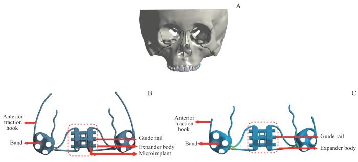
而后,基于初步构建的上颌复合体模型中第一磨牙间牙弓宽度及牙列大小,并参考临床扩弓器与前方牵引矫治器的尺寸,本研究应用Solidworks 2021软件分别生成骨支抗式快速扩弓联合前方牵引、牙支持式快速扩弓联合前方牵引的三维有限元模型。其中,牙支持式快速扩弓联合前方牵引装置由扩弓器主体、导轨、前牵引钩和双侧上颌第一磨牙上的带环构成,骨支抗式快速扩弓联合前方牵引装置则在上述部件的基础上向扩弓器主体引入2颗微种植钉;同时,2种快速扩弓器的前牵引钩均由双侧上颌第一磨牙带环颊侧伸出。

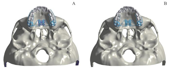
最终,将上述2种快速扩弓联合前方牵引装置分别与上颌复合体模型进行组装,并导入Ansys workbench 2021软件中,以建立上颌复合体和骨支抗式快速扩弓联合前方牵引三维有限元模型(模型1)、上颌复合体和牙支持式快速扩弓联合前方牵引三维有限元模型(模型2)。

1.3 模型的条件设置

根据既往文献9-11,本研究对上述构建的模型1和模型2中的材料参数进行设置,具体见表1。为方便计算,本研究不考虑材料内部结构中的非均质性,即将模型中各种材料均简化为均质、各向同性的线弹性体。

表1   模型1和模型2中各种材料的杨氏模量与泊松比

Tab 1  Young′s modulus and Poisson′s ratio of various materials in Model 1 and Model 2

MaterialYoung′s modulus/(N·mm-2)Poisson′s ratio
Craniofacial bones13 4000.30
Sutures700.40
Maxillary dentition20 7000.30
Expander190 0000.33
Microimplant113 0000.33

新窗口打开| 下载CSV


依据既往文献12,本研究对模型1和模型2的接触条件进行设置,即将皮质骨与骨缝间、牙与牙周膜间、牙周膜与上颌骨间、微种植钉与上颌骨间、带环与上颌第一磨牙间的界面设置为绑定接触,将导轨和扩弓器主体间设置为无摩擦,将相邻牙体间、前牵引钩与上颌牙列间的摩擦系数设置为0.2。

1.4 坐标系及上颌牙列的位移趋势设置

以腭中缝作为原点建立统一坐标系,X轴为水平向,以模型左侧为正、右侧为负;Y轴为矢状向,以模型后方为正、前方为负;Z轴为垂直向,以模型上方为正、下方为负。同时,本研究使用该统一坐标系来描述中切牙、第一磨牙的位移趋势,XYZ轴正方向分别代表中切牙牙冠向近中、腭向、压低位移,第一磨牙牙冠向腭向、远中、压低位移;XYZ轴负方向分别代表中切牙牙冠向远中、唇向、伸长位移,第一磨牙牙冠向颊向、近中、伸长位移。

1.5 施加载荷

根据既往文献13,本研究于模型1和模型2中的扩弓器两侧沿水平向分别施加0.25 mm的强制位移,并于快速扩弓联合前方牵引装置双侧的牵引钩处施加与平面呈30°角向下的牵引力,力的大小为5N/侧。

1.6 工况设置

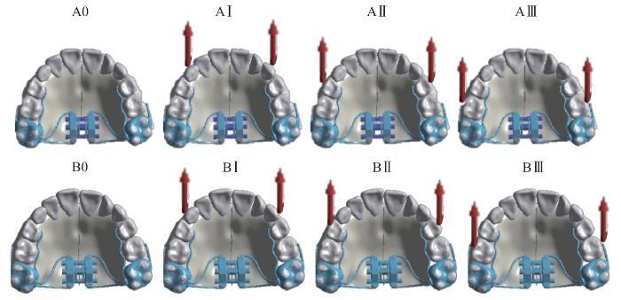
基于快速扩弓方式的不同,将模型1设置为A组、模型2设置为B组;而后,考虑到牵引位置的不同,我们将A、B组继续分为3个亚组(记为试验组),即将牵引钩位于双侧尖牙颊侧记为Ⅰ组、位于双侧第一前磨牙颊侧记为Ⅱ组、位于双侧第二前磨牙颊侧记为Ⅲ组。同时,分别将A、B组中不联合前方牵引设置为对照组,即为A0组、B0组。最终,本研究共建立了8个工况,即工况1~8依次为A0、AⅠ、AⅡ、AⅢ、B0、BⅠ、BⅡ、BⅢ(图1)。

图1

图1   模型1和模型28个工况设置

Note: Red arrows represent traction sites and directions.

Fig 1   Eight conditions of Model 1 and Model 2


1.7 观察指标

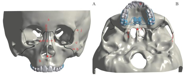
选取如下对象(图2)对模型1、模型2进行观察:① 颅颌面骨骼,包括额骨、上颌骨、颧骨、鼻骨。② 颅颌面骨骼点,包括后鼻嵴点(posterior nasal spine,PNS)、前鼻嵴点(anterior nasal spine,ANS)。③ 颅颌面骨缝,包括鼻额缝、颧颌缝、颧颞缝、颧额缝、翼突上颌缝、鼻中缝、鼻颌缝。④ 上颌牙列,包括上颌中切牙、第一磨牙。由于模型1、模型2为左右对称结构,因此仅对右侧模型进行测量,并对该2个模型的颅颌面骨缝应力分布特征(包括等效应变、最大主应变)以及颅颌面骨骼点、颅颌面骨骼、上颌牙列的位移趋势进行分析。

图2

图2   模型的观测对象的示意图

Note: A. Anterior aspect of the model. B. Inferior aspect of the model. a—frontal bone; b—maxilla; c—zygomatic bone; d—nasal bone; e—ANS; f—PNS; g—nasofrontal suture; h—zygomaticomaxillary suture; i—zygomatic temporal suture; j—zygomatic frontal suture; k—pterygomaxillary suture; l—nasal suture; m—nasomaxillary suture; n—maxillary central incisors; o—maxillary first molars.

Fig 2   Schematic diagram of observation objects of the model


2 结果

2.1 三维有限元模型的构建

本研究基于研究对象的CBCT图像,运用Mimics 21.0、Geomagic studio 2021、Solidworks 2021、Ansys workbench 2021软件等,依次成功构建了上颌复合体三维有限元模型(图3A)、2种(骨支抗式、牙支持式)快速扩弓联合前方牵引三维有限元模型(图3B、3C),以及模型1、模型2(图4)。同时,模型1和模型2的几何相似性和精确度均较高,即模型1有节点数793 140个、单元数451 826个,模型2有节点数753 625个、单元数428 778个。

图3

图3   上颌复合体三维有限元模型和2种快速扩弓联合前方牵引三维有限元模型图示

Note: A. Three-dimensional finite element model of maxillary complex. B. Three-dimensional finite element model of bone-anchored rapid expansion with protraction. C. Three-dimensional finite element model of tooth-borne rapid expansion with protraction.

Fig 3   Diagram of the three-dimensional finite element model of maxillary complex and two rapid expanders with protraction


图4

图4   模型1A)及模型2B)图示

Fig 4   Diagram of Model 1 (A) and Model 2 (B)


2.2 颅颌面骨缝应力分布特征的分析

2.2.1 骨缝等效应变的分析

通过计算试验组等效应变与其对应的对照组等效应变的比值来描述骨缝等效应变的变化趋势,比值越大则骨缝等效应变越大。如图5所示,A、B组中翼突上颌缝等效应变最大,且随着牵引位置的后移其等效应变均逐渐增加。

图5

图5   骨支抗式扩弓联合前方牵引(A)和牙支持式扩弓联合前方牵引(B)的试验组与对照组骨缝等效应变的比值

Fig 5   Experimental group-to-control group ratio of sutures′ equivalent strain of bone-anchored rapid expander with protraction (A) and tooth-borne rapid expander with protraction (B)


2.2.2 骨缝最大主应变的分析

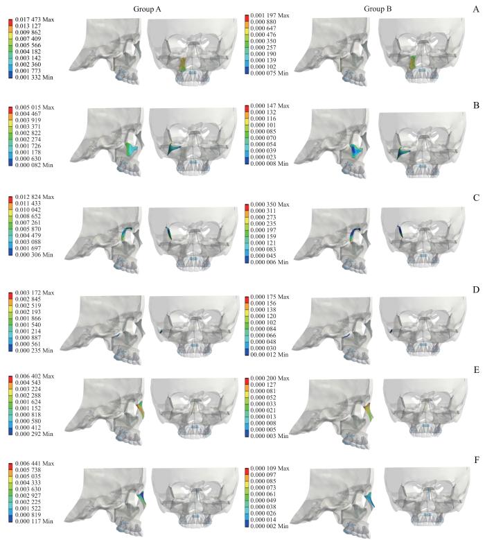
在三维应力状态下,最大主应变力为材料中承受的最大拉伸应力或压缩应力。在本研究中最大主应变代表骨缝的拉伸情况,可提示潜在的应力集中区域。因此,我们以在Ⅰ处牵引(AⅠ、BⅠ)来代表A、B组的情况进行展示。图6为AⅠ、BⅠ组各骨缝的最大主应变示意图。通过图例上标尺的数量级可看出:AⅠ组各骨缝最大主应变均大于BⅠ组,翼突上颌缝的最大主应变均大于其他各骨缝,即AⅠ组各骨缝拉伸效应大于BⅠ组,翼突上颌缝的拉伸效应大于其余各骨缝。AⅠ组中翼突上颌缝的中上部分拉伸效应最大,即该部分成骨增加,进而出现上颌骨的顺时针旋转;BⅠ组中翼突上颌缝靠近模型下方的区域拉伸效应最明显,与AⅠ组结果相反,呈现上颌骨的逆时针旋转(图6A)。AⅠ组中鼻颌缝拉伸效应分布较均匀,最大值靠近模型后方;BⅠ组中鼻颌缝最大主应变的最大值出现在模型上方即鼻根附近(图6E)。与鼻颌缝相似,AⅠ组中鼻中缝拉伸效应集中在模型后方,BⅠ组中主要体现在鼻根附近(图6F)。

图6

图6   AⅠ、BⅠ组各骨缝的最大主应变图示(右视图及前视图)

Note: A. Pterygomaxillary suture. B. Zygomaticomaxillary suture. C. Zygomatic temporal suture. D. Zygomatic bone. E. Nasomaxillary suture. F. Nasofrontal suture. In scale label, positive value represents tensile stress, and negative value represents compressive stress. Based on the right and frontal views of the nasofrontal suture, which are represented as points and lines with relatively small values, no analysis was conducted on the nasofrontal suture in this area.

Fig 6   Diagram of sutures′ maximum principal strain of Group AⅠ and Group BⅠ (right view and front view)


2.3 颅颌面骨骼的三维方向位移趋势分析

2.3.1 颅颌面骨骼位移大小的总体变化

颅颌面骨骼位移大小的总体变化如表2~4所示,其中A组所有骨骼在3个方向上的位移均大于B组。水平向上(X轴),A、B试验组骨骼均表现为向右位移,其中额骨与上颌骨位移最大,鼻骨位移最小。矢状向上(Y轴),A、B试验组额骨和鼻骨均表现为向后位移,上颌骨和颧骨均表现为向前位移;A试验组中矢状位移量大小依次为额骨>鼻骨>颧骨>上颌骨,B试验组中骨骼矢状位移量大小依次为上颌骨>颧骨>额骨=鼻骨。垂直向上(Z轴),A、B试验组鼻骨均表现为向下位移,额骨、上颌骨、颧骨表现为向上位移。

表2   颅颌面骨骼在 X 轴上的位移/mm

Tab 2  Displacement of the cranio-maxillofacial bones along the X-axis/mm

Cranio-maxillofacial boneGroup AGroup B
A0AⅠAⅡAⅢB0BⅠBⅡBⅢ
Frontal bone-0.063 97-0.064 05-0.063 98-0.063 93-0.003 08-0.003 52-0.002 89-0.002 24
Maxilla-0.063 97-0.064 05-0.063 98-0.063 93-0.003 08-0.003 52-0.002 89-0.002 24
Zygomatic bone-0.045 22-0.045 16-0.045 05-0.044 98-0.001 53-0.001 67-0.001 33-0.000 99
Nasal bone-0.024 05-0.023 81-0.023 73-0.023 71-0.000 48-0.000 35-0.000 16-0.000 04

新窗口打开| 下载CSV


表3   颅颌面骨骼在 Y 轴上的位移/mm

Tab 3  Displacement of the cranio-maxillofacial bones along the Y-axis/mm

Cranio-maxillofacial boneGroup AGroup B
A0AⅠAⅡAⅢB0BⅠBⅡBⅢ
Frontal bone0.027 700.027 400.027 300.027 300.001 000.000 770.000 630.000 62
Maxilla-0.008 59-0.009 51-0.009 81-0.010 00-0.000 61-0.003 45-0.003 89-0.004 34
Zygomatic bone-0.009 50-0.009 87-0.009 98-0.010 01-0.000 27-0.001 05-0.001 26-0.001 42
Nasal bone0.024 600.024 400.024 250.024 210.000 930.000 770.000 560.000 37

新窗口打开| 下载CSV


表4   颅颌面骨骼在 Z 轴上的位移/mm

Tab 4  Displacement of the cranio-maxillofacial bones along the Z-axis/mm

Cranio-maxillofacial boneGroup AGroup B
A0AⅠAⅡAⅢB0BⅠBⅡBⅢ
Frontal bone0.026 510.026 100.025 800.025 700.001 100.000 640.000 320.000 31
Maxilla0.023 890.023 400.023 200.023 100.001 050.000 360.000 180.000 11
Zygomatic bone0.021 340.020 900.020 800.020 700.000 700.000 360.000 200.000 10
Nasal bone-0.018 22-0.018 00-0.017 80-0.017 70-0.000 70-0.000 63-0.000 35-0.000 07

新窗口打开| 下载CSV


2.3.2 颅颌面骨骼位移大小随牵引位置改变的变化趋势

在A、B试验组中,随着牵引位置的后移,水平向上(X轴)其鼻骨和上颌骨的向右位移均逐渐减少,矢状向上(Y轴)其鼻骨向后位移均逐渐减少、上颌骨向前位移均逐渐增加,垂直向上(Z轴)其鼻骨向下位移均逐渐减少、上颌骨向上位移亦均逐渐减少(表2~4)。

2.4 颅面骨骨骼点位移大小及其随牵引位置改变的变化趋势

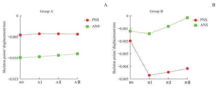
图7所示,垂直向上(Z轴),ANS、PNS均产生向下的位移。A0组中,ANS的向下位移大于PNS即上颌平面(ANS-PNS平面)发生顺时针旋转,且随着牵引位置的后移,A组ANS的向下位移减少、PNS的向下位移增加,表明上颌平面顺时针旋转趋势减小;B0组中,ANS的向下位移小于PNS即上颌平面发生逆时针旋转,且随着牵引位置的后移,ANS和PNS的向下位移相差逐渐增大,即上颌平面逆时针旋转趋势更加明显。

图7

图7   A组(A)、B组(B)的各骨骼点(ANSPNS)在垂直向上( Z 轴)的位移趋势

Fig 7   Displacement trend of each skeletal point (ANS, PNS) in Group A (A) and Group B (B) in the vertical direction (Z-axis)


2.5 上颌牙列位移随牵引位置改变的变化趋势

2.5.1 上颌中切牙位移随牵引位置改变的变化趋势

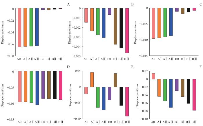
图8所示,A、B试验组上颌中切牙的位移趋势基本相同,即随着牵引位置的后移,水平向上上颌中切牙的远中位移趋势减小,矢状向上唇向位移趋势增加,垂直向上伸长位移趋势减小。

图8

图8   AB组上颌中切牙和上颌第一磨牙的三维方向的位移分析

Note: A‒C. Displacement analysis of maxillary central incisor in the horizontal direction (A), sagittal direction (B) and vertical direction (C). D‒F. Displacement analysis of maxillary first molar in the horizontal direction (D) sagittal direction (E) and vertical direction (F).

Fig 8   Three-dimensional displacement analysis of maxillary central incisors and maxillary first molars in Group A and Group B


2.5.2 上颌第一磨牙位移随牵引位置改变的变化趋势

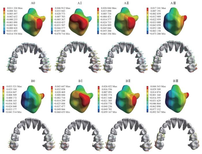
如图89所示:水平向上A、B组上颌第一磨牙均表现为颊向位移,且随着牵引位置的后移其位移趋势增大。矢状向上A0、B0组上颌第一磨牙均表现为近中位移,当前方牵引施加于Ⅰ处时A、B组上颌第一磨牙均表现为远中位移,于Ⅱ处时则变为近中位移,且随着牵引位置的后移其近中位移趋势增大;与此同时,在位移量上,Ⅰ处牵引时A组第一磨牙比B组发生远中位移的更多,在Ⅱ、Ⅲ处牵引时A组第一磨牙比B组发生近中位移的更少。垂直向上仅A0组上颌第一磨牙表现为压低位移,其余7组均表现为伸长位移,且随着牵引位置的后移上颌第一磨牙伸长趋势逐渐增大。

图9

图9   AB组的上颌第一磨牙的位移趋势图示

Note: The color of the arrow represents the magnitude of displacement, and the direction of the arrow represents the direction of displacement.

Fig 9   Diagram of the displacement trend of the maxillary first molar in Group A and Group B


3 讨论

研究14发现,上颌快速扩弓联合前方牵引可有效改善骨性Ⅲ类错患者的后牙反,打开骨缝并促进上颌骨向前下生长,进而改变上下颌骨矢状向的相对位置,从而提高其治疗效果。近年来的多项研究15-16表明,相较于牙支持式快速扩弓,骨支抗式快速扩弓联合前方牵引可使上颌骨向前生长更为明显,不仅能改变上颌骨旋转方向,还可有效防止上磨牙伸长、前移、颊倾以及上前牙唇倾等不利的牙齿代偿效应。基于此,本研究模拟临床最常用的前方牵引角度(向下、向前30°),探索于不同前方牵引位置时骨支抗式、牙支持式快速扩弓对颅颌面骨缝、骨骼点、骨骼及上颌牙列的影响。

3.1 骨缝等效应变

等效应变是指物体在受到外力作用时发生的形变,其与等效应力都可用来描述受力物体的形变大小。本研究发现,A、B组的各骨缝中翼突上颌缝的等效应变最大且A组均大于B组,提示骨支抗式快速扩弓联合前方牵引更有利于促进上颌骨的向前方生长;随着牵引位置的后移,2组翼突上颌缝等效应变均逐渐增大,且在Y轴上上颌骨向模型前方位移趋势也逐渐增大,由此推测翼突上颌缝等效应变与上颌骨向前方位移趋势变化可能呈正相关。

3.2 骨缝最大主应变

最大主应变可反映骨缝的拉伸效应。本研究发现:AⅠ组中颧颌缝、颧额缝、颧颞缝靠近模型后方拉伸明显,即与骨缝后方相连的骨骼生成量较大;BⅠ组中颧颌缝、颧额缝、颧颞缝拉伸效应均集中于靠近上颌后牙一侧,可能与牙支持式扩弓产生的牙性效应相关。在AⅠ组中,翼突上颌缝中上方拉伸效应明显,成骨增加,进而出现上颌骨的顺时针旋转;与AⅠ组相反,BⅠ组呈现了上颌骨的逆时针旋转。提示骨支抗式快速扩弓联合前方牵引会导致上颌平面发生顺时针旋转,牙支持式快速扩弓联合前方牵引可导致上颌平面发生逆时针旋转;鼻颌缝和鼻中缝在2组中均为后方拉伸效应明显,即鼻骨生长呈现楔形效应,四周鼻骨逐渐向前生长,中心鼻骨相对位移向后。

3.3 骨骼在三维方向的位移及位移趋势

骨性Ⅲ类错患者常存在上颌骨发育不足、鼻基底凹陷等问题,因此探索出不仅能够有效促进上颌骨向前生长且同时可改善鼻基底凹陷的最佳前方牵引方式具有重要的临床意义。本研究发现,A、B试验组中骨骼位移趋势基本相同,即随着牵引位置的后移,矢状向上上颌骨向前位移均逐渐增加,鼻骨向后位移均逐渐减少;这提示对于存在鼻基底凹陷的上颌骨发育不足患者,临床施加前方牵引的位置应尽量放于上颌牙列后侧。

3.4 骨骼点在三维方向的位移及位移趋势

根据骨骼点ANS、PNS在垂直向上(Z轴)的位移方向和大小可判断上颌平面的旋转方向17。本研究发现:A组中上颌平面发生了顺时针旋转,有利于开患者的矫治;B组中上颌平面发生了逆时针旋转,有利于反覆较深的患者的矫治。而随着牵引位置的后移,A组顺时针旋转的趋势减小,B组逆时针旋转的趋势增加。因此,在使用2种快速扩弓联合前方牵引时,对于反覆严重者牵引位置应尽量位于牙列后方,对于前牙开严重者牵引位置应尽量位于牙列前方。

3.5 上颌牙列在三维方向的位移及位移趋势

本研究发现:在矢状向上随着牵引位置的后移,A、B试验组第一磨牙从远中位移(AⅠ)转为近中位移(AⅡ、AⅢ),这可能是由于随着牵引钩位置的后移,第一磨牙受力的力臂逐渐减小,力矩也减小,导致其远中位移转为近中位移;同时,在Ⅰ处牵引时A组第一磨牙比B组发生远中位移的更多,在Ⅱ、Ⅲ处牵引时A组第一磨牙比B组发生近中位移的更少。这提示骨支抗式快速扩弓联合前方牵引有利于减少第一磨牙的近中位移,适合于后牙段存在拥挤的患者。此外,我们还发现A、B试验组中第一磨牙均表现为颊倾、伸长位移,因此临床上对于下颌平面角偏大的患者需谨慎使用骨支抗式和牙支持式快速扩弓矫治器,以防止第一磨牙进一步伸长、下颌平面角进一步增大,必要时需使用后牙垫式扩弓器。

综上,本研究发现随着牵引位置向后移动,上颌骨向前位移量逐渐增加。同时,根据骨骼点ANS、PNS位移变化我们还发现,A组中上颌平面发生了顺时针旋转,有利于开患者的矫治;B组中上颌平面发生了逆时针旋转,有利于反覆较深的患者的矫治。随着临床上骨支抗式和牙支持式快速扩弓的普遍应用,不同类型的青少年骨性Ⅲ类错患者可选择的矫治方法也越来越多,因此未来可探索更多临床因素对该2种矫治器矫治效果的影响。

作者贡献声明

韩磊参与了研究设计、数据收集、统计分析和文章撰写;鲁桐和朱培香参与了数据收集、统计分析和文章撰写;李煌参与了研究设计和文章审阅。所有作者均阅读并同意了最终稿件的提交。

AUTHOR's CONTRIBUTIONS

HAN Lei participated in the research design, data collection, statistical analysis and manuscript writing. LU Tong and ZHU Peixiang participated in the data collection, statistical analysis and manuscript writing. LI Huang participated in the research design and manuscript review. All the authors have read the last version of paper and consented for submission.

利益冲突声明

所有作者声明不存在利益冲突。

COMPETING INTERESTS

All authors disclose no relevant conflict of interests.

参考文献

TURLEY P K. Orthopedic correction of Class Ⅲ malocclusion with palatal expansion and custom protraction headgear[J]. J Clin Orthod, 1988, 22(5): 314-325.

[本文引用: 1]

JHA A K, CHANDRA S. Early management of class Ⅲ malocclusion in mixed dentition[J]. Int J Clin Pediatr Dent, 2021, 14(2): 331-334.

[本文引用: 1]

谷岩, RABIE A, HÄGG U. 前方牵引器治疗安氏Ⅲ类错 畸形: 20例病例临床分析[J]. 口腔正畸学, 2000, 7(3): 118-122.

[本文引用: 1]

GU Y, RABIE A, HÄGG U. Treatment effects of reverse-headgear in correction of Angle Class Ⅲ malocclusion[J].Journal of Orthodontics, 2000, 7(3): 118-122.

[本文引用: 1]

NGAN P, HÄGG U, YIU C, et al. Soft tissue and dentoskeletal profile changes associated with maxillary expansion and protraction headgear treatment[J]. Am J Orthod Dentofacial Orthop, 1996, 109(1): 38-49.

[本文引用: 1]

KASAI K. Soft tissue adaptability to hard tissues in facial profiles[J]. Am J Orthod Dentofacial Orthop, 1998, 113(6): 674-684.

[本文引用: 1]

CANTARELLA D, DOMINGUEZ-MOMPELL R, MALLYA S M, et al. Changes in the midpalatal and pterygopalatine sutures induced by micro-implant-supported skeletal expander, analyzed with a novel 3D method based on CBCT imaging[J]. Prog Orthod, 2017, 18(1): 34.

[本文引用: 1]

CORNELIS M A, TEPEDINO M, RIIS N V, et al. Treatment effect of bone-anchored maxillary protraction in growing patients compared to controls: a systematic review with meta-analysis[J]. Eur J Orthod, 2021, 43(1): 51-68.

[本文引用: 1]

DE SOUZA R A, NETO J R, DE PAIVA J B. Maxillary protraction with rapid maxillary expansion and facemask versus skeletal anchorage with mini-implants in class Ⅲ patients: a non-randomized clinical trial[J]. Prog Orthod, 2019, 20(1): 35.

[本文引用: 1]

SURESH S, SUNDARESWARAN S, SATHYANADHAN S. Effect of microimplant assisted rapid palatal expansion on bone-anchored maxillary protraction: a finite element analysis[J]. Am J Orthod Dentofacial Orthop, 2021, 160(4): 523-532.

[本文引用: 1]

MENG W Y, MA Y Q, SHI B, et al. The comparison of biomechanical effects of the conventional and bone-borne palatal expanders on late adolescence with unilateral cleft palate: a 3-dimensional finite element analysis[J]. BMC Oral Health, 2022, 22(1): 600.

YOON S, LEE D Y, JUNG S K. Influence of changing various parameters in miniscrew-assisted rapid palatal expansion: a three-dimensional finite element analysis[J]. Korean J Orthod, 2019, 49(3): 150-160.

[本文引用: 1]

LIU Z, SUN T H, FAN Y B. Biomechanical influence of anchorages on orthodontic space closing mechanics by sliding method[J]. Med Biol Eng Comput, 2020, 58(5): 1091-1097.

[本文引用: 1]

白璐, 包涵, 谢宁, 等. 三种快速扩弓联合前方牵引装置作用效果的三维有限元分析[J]. 口腔医学, 2021, 41(1): 32-37.

[本文引用: 1]

BAI L, BAO H, XIE N, et al. Effects of three types of rapid maxillary expansion with protraction appliances: a three-dimensional finite element analysis[J]. Stomatology, 2021, 41(1): 32-37.

[本文引用: 1]

AL-MOZANY S A, DALCI O, ALMUZIAN M, et al. A novel method for treatment of Class Ⅲ malocclusion in growing patients[J]. Prog Orthod, 2017, 18(1): 40.

[本文引用: 1]

韩磊, 李佳岭, 李保超, 等. 两种快速扩弓方式联合前方牵引治疗骨性Ⅲ类错 的疗效差异分析[J]. 中华口腔医学杂志, 2023, 58(4): 318-328.

[本文引用: 1]

HAN L, LI J L, LI B C, et al. Comparison of two different methods of rapid expansion combined with maxillary protraction in the treatment of skeletal class Ⅲ malocclusion[J]. Chinese Journal of Stomatology, 2023, 58(4): 318-328.

[本文引用: 1]

LEE Y S, PARK J H, KIM J, et al. Treatment effects of maxillary protraction with palatal plates vs conventional tooth-borne anchorage in growing patients with Class Ⅲ malocclusion[J]. Am J Orthod Dentofacial Orthop, 2022, 162(4): 520-528.

[本文引用: 1]

黄家昕, 张晓蓉, 姚激. 平行于功能 平面水平向后牵引猴上颌骨矫形作用的三维有限元研究[J]. 华西口腔医学杂志, 2014, 32(2): 196-199.

[本文引用: 1]

HUANG J X, ZHANG X R, YAO J. 3D finite-element study on displacement of craniofacial complex with retractive forces parallel to the occlusion plane on the maxilla of rhesus monkeys[J]. West China Journal of Stomatology, 2014, 32(2): 196-199.

[本文引用: 1]

/